 0
 0
Installing a constant air volume (CAV) damper correctly is one of the most frequent questions raised by designers, engineers, and installers working on air conditioning and ventilation projects. Because airflow changes with duct pressure variations, the physical placement of a CAV damper directly affects whether a system can maintain steady supply or exhaust airflow without repeated on-site balancing. Reviewing the documented installation guidance for Meridel's CAV product range—spanning the Meridel CAV series (CAVC, CAVP) and the associated CAV terminal and controller series (CAV terminal units, RN, RN-Ex, VFC, VFL, and retrofit kits)—provides a clear picture of where and how these self-powered mechanical dampers should be positioned.
Understanding CAV Damper Installation Requirements in HVAC Systems
All of these products share a common engineering principle: a mechanical self-powered constant volume mechanism combining a damper blade, bellows or airbag, leaf spring, and cam plate that maintains a set airflow without external power. Because this mechanism depends on consistent airflow entering the device, installation location and upstream straight-duct length are critical variables addressed throughout the product documentation.
CAV Constant Air Volume Regulating Damper: Duct-End Installation
The CAVC constant air volume regulating damper is positioned at the duct end, where it removes the need for manual pressure balancing for supply or exhaust air. Its working temperature range is 10 to 50 °C, with a differential pressure range of 50 to 1000 Pa and a flow range of 4:1. The product requires a straight inflow of at least 1.5D upstream to function accurately.
CAV-Q Installation (Quadrate)
For the quadrate version, flanges on both ends are used, with compressible sealing material recommended. Installation calls for a minimum of 1.5W straight duct upstream and 0.5W straight duct downstream, where W represents the damper width.
CAV-R Installation (Circular)
The circular version is fixed to the spigot using self-tapping screws or air-tight blind rivets, requiring a minimum of 1.5R straight duct upstream. The seal lip may be lubricated during installation, and custom-sized duct production is available when required.
CAV Plastic Constant Air Volume Regulating Damper: Circular Duct Insertion
The CAV plastic constant air volume regulating damper is designed for circular ducts and is intended to be set at the installation site and inserted directly into the duct, offering an economical and simple air volume balancing method. For optimal noise performance, the intake straight pipe length should exceed 1.5D, and sufficient pipe sections should be provided for steady flow when the duct diameter changes. Nominal sizes range from 80, 100, 125, 160, 200, to 250 mm, with a control accuracy of about 10% across a 30 to 300 Pa differential pressure range.
CAV Terminal Units: Installation in Potentially Explosive Atmospheres
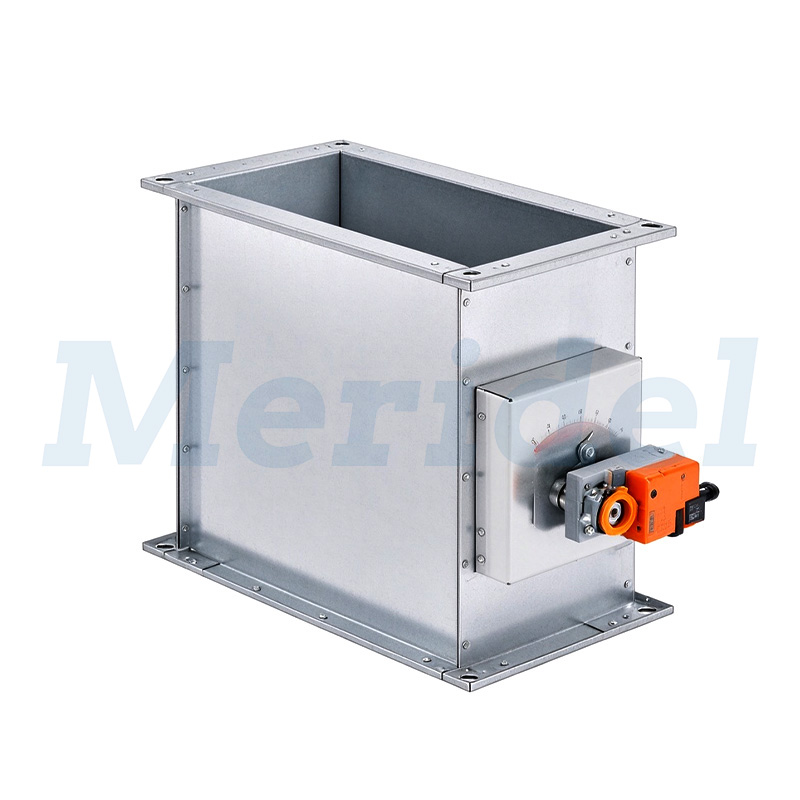
For installations involving potentially explosive atmospheres, the Constant Volume Flow Control CAV terminal units are rectangular, mechanically self-powered, and ATEX equipment-group II approved for zones 1, 2, 21, and 22. Installation guidance specifies horizontal airflow, and the operating side must not point upward. Upstream conditions require a straight duct section of at least 1.5B after bends, 1.5B or 1.5H after junctions, and 1.5B or 1.5H straight upstream for free air intake. Equipotential bonding connections must be made on the customer side, and nominal sizes range across 19 sizes from 200 × 100 to 600 × 600 mm.
RN and RN-Ex Controllers: Circular Duct Placement for Standard and ATEX Applications
The circular CAV controllers RN are designed for any installation orientation and are maintenance-free, suitable for airflow velocities up to 12 m/s. Upstream, free air intake requires 1D straight duct, while a junction from the main duct requires at least 1.5D straight upstream; a bend with a radius of at least 1D has negligible effect on performance. Nominal sizes span 80 to 400 mm, including the RN-S compact height and RN-FL flanged variants.
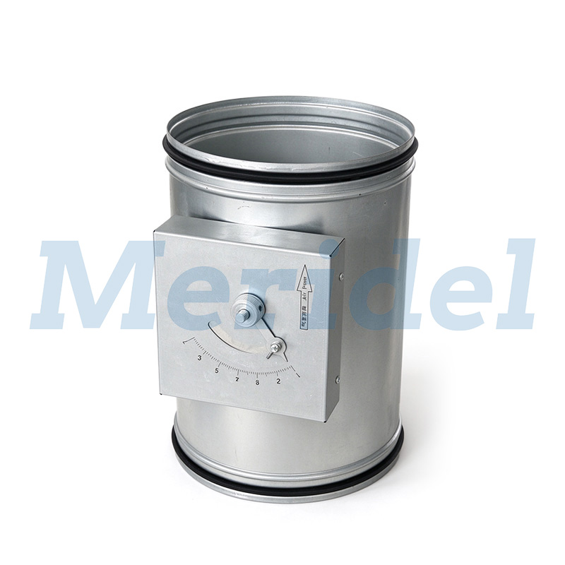
The RN-Ex version follows the same circular installation logic but is built for potentially explosive atmospheres, carrying the type examination certificate TUV 05 ATEX 7159 X. Construction follows EN 1506 or EN 13180, with a circular casing and spigot with insert bead for lip seal. As with RN, acoustic cladding variants (RN-Ex-D) cannot be retrofitted, meaning the installation configuration must be decided before ordering.
VFC Controllers: Low-Velocity Airflow Installation
The CAV controllers VFC are suited to low airflow velocities starting from 0.8 m/s and, like RN, allow any installation orientation while remaining maintenance-free. Upstream requirements mirror the RN series: 1D straight duct for free air intake, and at least 1.5D straight upstream for a junction from the main duct. Nominal sizes range from 80 to 250 mm, and the unit supports retrofit actuators (E01, E02, M01, M02 for min/max; E03 for modulating control) for installations that later require variable volume flow.
VFL Volume Flow Limiter: Quick Insertion Balancing
The Constant Volume Flow Control CAV controllers VFL is an insertion volume flow limiter for circular ducting, intended to simplify what has traditionally been tedious and costly duct flow balancing. Installation involves setting the flow on a scale, inserting the unit into the duct, and marking the installation location. Free air intake requires 1D straight duct, and duct connections must comply with EN 1505. Nominal sizes include 80, 100, 125, 150, 160, 200, and 250 mm, with the nominal size 150 using a different damper blade construction and volume flow rate sticker.
Why Installation Location Matters: Industry Certifications and Compliance
Across the entire range, installation guidance is tied directly to compliance outcomes. Units are tested for casing air leakage to EN 1751, Class C, and conform to VDI 6022 hygiene requirements. The ATEX-rated products—CAV terminal units and RN-Ex—carry ATEX equipment-group II approval for zones 1, 2, 21, and 22, which depends on correct orientation, bonding, and upstream duct conditions being respected during installation. Each unit also undergoes factory aerodynamic functional testing on a special test rig and, for KST CAVC, factory calibration using a standard calibration table of the National Testing Center before shipment, reducing the need for repeated on-site measurement once correctly positioned.
In summary, the correct installation point for a CAV damper—whether at a duct end, within a circular duct run, or as a rectangular terminal unit in an explosive atmosphere—depends on the specific product type within the Meridel CAV range. Following the documented upstream straight-duct lengths, orientation rules, and sealing methods allows these self-powered mechanical regulators to maintain their set airflow without external power or repeated commissioning adjustments, supporting standard-compliant HVAC installations, including ATEX environments.
https://meridel-air.com/
Meridel


Average Rating